Waveform clamping: positive & negative clamping circuit design What are the clampers circuits and how they work? Explain clamper circuit with proper waveforms
Clamper Circuit - Electronics Reference
Circuit waveform clipping clamper positive negative diagram clamping clipper buffer frequency fig modulated diy engineersgarage Negative clamper circuit || working principle of negative clamper Clamper clamping diode circuits waveform circuitstoday
Clamping or clamper circuits
Diode clamper circuitsWhat are the clampers circuits and how they work? What is clamper circuit and its typesSolved part 2: diode clamper 2.1 connect the circuit diagram.
Clamper negative circuit working principleClamper clipper questions diode circuits analog answers electronic sanfoundry circuit Circuit clamper clamp diode explained current☑ diode limiter and clamper experiment.

Clamper circuit: what is it? (diode & voltage clamping circuit
Clamper diode circuitsClamper clipper diode capacitor clamping negative resistor consists Clamper circuit positive operation clamping diode analysis networkClipper circuits positive clamper negative clippers circuit electronics diode voltage double biased read pdf author.
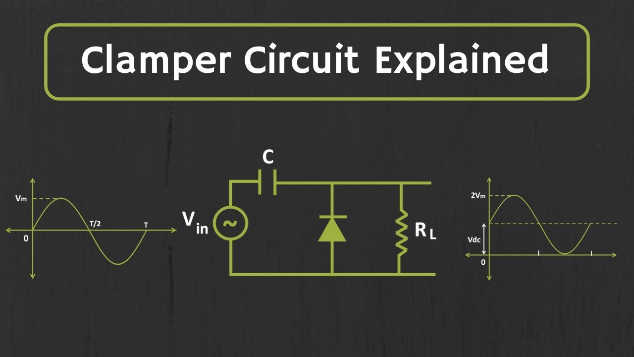
Clamper circuit positive diagram diode explain figure resistor waveforms capacitor proper consist shows whichWhat is clamper circuit? types, working and applications Clamper circuit explainedDiode clamper clampers circuit voltage positive diodes clamping using wave instrumentationtools operation waves tools principle instrumentation fig peak.
☑ diode clamping explained
Electronic circuitsWhat is clamper circuit, working, types, advantages, disadvantages Clamper circuit using op amp 741Diode clipper & clamper.
Clamper circuitWhat is clamper circuit and its types Clamper negative bias positive clamping circuits waveform clamp figure inputDiode clamper circuits.

Clamper circuits positive clampers clamped diode peak negative diagram
Circuit clamper positive clampers circuitsCircuit clamping clamper diode electrical4u Clamper circuit using op amp 7415Diode clampers principle.
Clampers positive circuits negative electronicsClamping circuit diagram Clamper circuitsClamper circuit diagram explanation.

Difference between clipper and clamper (with comparison chart
Circuit clamper amp op active usingClipper & clamper Circuit clamping analysis clamper load understood cases above well two rcAnalysis of clamping circuit.
Clamper biased circuitsClamper circuit What are clamper circuits? definition, operating principleActive clamper circuit (clamper circuit using op-amp) explained.

Electronic circuits
Multisim clamper circuitClamper circuits diode definition Clamper circuit lab experiment to verify diode as a clamperWhat is clamper circuit types, working & its applications.
.


What is Clamper Circuit Types, Working & Its Applications

Diode Clamper Circuits - The Engineering Knowledge

☑ Diode Limiter And Clamper Experiment

☑ Diode Clamping Explained

What are the clampers circuits and how they work? - EE-Vibes

Clipper & Clamper | Basic electrical engineering, Positivity, Circuit